UML gives a software design several complementary views. Choose the diagram family for the question you want to answer: a class diagram explains types and relationships, a sequence diagram explains an interaction, and a deployment diagram explains where artifacts run.
Visual Nerve provides an editable example for each of the 14 UML diagram families and a shared symbol collection based on UML 2.5.1. Choose New diagram → UML · …, or use Notation collections → UML inside an ordinary diagram.
Choose a structural view
| Family | Use it to explain | What the example demonstrates |
|---|---|---|
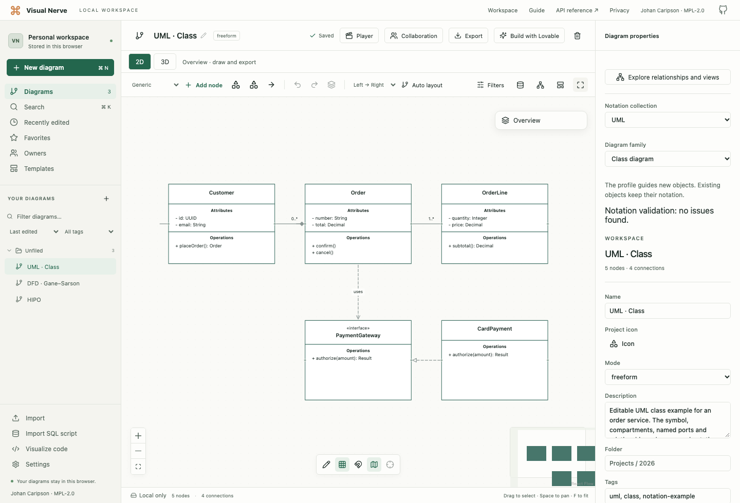
| Class | Types, features and static relationships | Customer, Order and OrderLine attributes/operations, composition, multiplicity and an interface realization |
| Object | Particular instances at one moment | A specific order and its populated line-item slots |
| Package | Organization and dependencies between namespaces | Domain and API packages with members and an imported shared package |
| Component | Replaceable units and their interfaces | Checkout, order service, payment adapter, a port and a provided contract |
| Composite Structure | Parts and connectors inside a classifier | Checkout and payment parts inside OrderService, with an attached port |
| Deployment | Runtime nodes and deployed artifacts | A client device and an application server containing a runtime and service artifact |
| Profile | Vocabulary that extends UML | A Service stereotype extending the Component metaclass, with properties |
Use class compartments for declarations such as - total: Decimal or + confirm(). Object slots instead show values, such as total = 48.00. A package groups model elements; a deployment node represents a runtime resource or environment.
Choose a behavioral or interaction view
| Family | Use it to explain | What the example demonstrates |
|---|---|---|
| Use Case | A subject’s capabilities from an actor’s perspective | Customer and an order-service boundary, with include and extend relationships |
| Activity | Actions, control choices and carried objects | Review, accepted/rejected paths, an object result and an activity final |
| State Machine | A subject’s states and responses to events | Draft, Submitted and Shipped, with trigger, guard and effect |
| Sequence | Messages ordered along participants’ lifelines | Order placement and payment authorization, executions and replies |
| Communication | Collaborating objects and numbered messages | Linked participants with messages 1 and 1.1 |
| Interaction Overview | Control flow between interactions | Referenced checkout/payment interactions and a rejection branch |
| Timing | State changes and interactions against time | Order and payment timing lifelines with a stated time range |
An activity follows work through actions; a state machine follows one subject through states. Sequence and communication describe interactions from different perspectives. Timing makes the time axis explicit. The examples are authored designs; their messages and time ranges are not measurements from a running system.
Choose a UML symbol
These grouped references cover the collection’s 79 symbol choices. Choose the meaning first, then the shape. Similar-looking boxes can describe a type, an instance, a role or a runtime resource; their names, keywords and entries make the distinction visible.
Types, instances and association details
| Choice | Use it when |
|---|---|
| Class; Object / instance specification | A Class describes a type’s features; an Object / instance specification describes a particular instance and its slot values. Use Order for the type and order42: Order for an instance. |
| Interface | You specify a contract of public features that another classifier realizes. It describes what is offered rather than an implementation. |
| Enumeration; Data type | An Enumeration names a finite set of literals, such as order statuses. A Data type describes values, such as a money amount, whose identity is not the modeling concern. |
| Association class | A relationship itself needs attributes or operations, such as an Enrollment linking Student and Course with a registration date. Connect the classifier to the association explicitly. |
| Template classifier | A reusable classifier has formal parameters. Put them in the parameter section, and use a Template binding relationship for actual arguments. |
| Association qualifier | A value such as an account number selects associated instances. Place the qualifier at the appropriate association end and write the selection key. |
| N-ary association | One association relates three or more participants. Connect each participant to the central association rather than implying several independent binary relationships. |
Components, organization and deployment
| Choice | Use it when |
|---|---|
| Component; Part / property | A Component is a modular unit with contracts. A Part / property describes a role within a structured classifier, such as its payment: PaymentAdapter part. |
| Port | A classifier needs a named interaction point on its boundary. Attach it to its owner and connect through that point. |
| Provided interface; Required interface | A Provided interface states a service offered by a component or port; a Required interface states a service it needs. The circle and socket express opposite roles. |
| Collaboration | Several roles cooperate to perform a function. Use parts and connectors to explain the participating roles rather than treating the collaboration as a deployed component. |
| Package; Model | A Package organizes named elements. A Model is a package used as a model’s scope; its «model» keyword distinguishes that purpose. |
| Profile; Stereotype | A Profile groups extensions to UML vocabulary. A Stereotype defines one extension and its properties or constraints; connect it to the extended metaclass with Stereotype extension. |
| Node; Device; Execution environment | A Node is a computational resource. A Device is a physical resource; an Execution environment is a software environment hosting execution, such as an application runtime. |
| Artifact | A deployable information item, such as a service binary or configuration file, needs to be distinguished from the component it implements and the node hosting it. |
Use cases
| Choice | Use it when |
|---|---|
| Actor | A role outside the subject interacts with it. An actor can be a person, another system or another external role. |
| Use case | You describe a capability offered to an actor, such as Place order, rather than an internal processing step. |
| Subject / system boundary | You identify the subject whose capabilities are being described. Place its use cases inside and external actors outside. |
| Extension points | You name positions in a use case where extending behavior may be inserted. Pair the names with an Extend relationship and its stated condition. |
Activities and actions
| Choice | Use it when |
|---|---|
| Activity; Action | An Activity describes a behavior composed of connected nodes. An Action is an executable step within that behavior, such as Validate order. |
| Activity parameter node | You show an input or output of the whole activity. Place it on the activity boundary; it differs from an individual action’s pin. |
| Object node; Central buffer; Data store | An Object node carries objects or values through an activity. A Central buffer mediates flows between nodes. A Data store retains tokens so downstream use does not consume the stored information. |
| Input pin; Output pin | An action needs explicit inputs or outputs. Attach the pin to that action and connect object flows to it. |
| Expansion region; Expansion node | A region applies behavior to the elements of a collection. Expansion nodes identify the collections crossing its boundary; state whether processing is iterative, parallel or streaming. |
| Initial node; Activity final; Flow final | An Initial node starts activity flow. An Activity final ends the whole activity; a Flow final ends only the flow reaching it. |
| Decision; Merge | A Decision chooses an alternative using guards. A Merge reunites alternative flows without synchronizing concurrent paths. |
| Fork; Join | A Fork creates concurrent flows. A Join synchronizes them; it differs from a Merge of alternatives. |
| Activity partition / swimlane | You group activity nodes by responsibility or another shared characteristic. Crossing a partition does not by itself send a message. |
| Interruptible activity region | Work in a region can be abandoned through an Interrupting activity edge. Draw the region and the interrupting exit explicitly. |
| Exception handler | You identify behavior that handles an exception from a protected activity node. Use Exception flow to show the handler route and name the handled exception. |
| Send signal action; Accept event action; Accept time event action | Send signal action emits an asynchronous signal. Accept event action waits for a matching event; Accept time event action waits for a time condition. |
States and pseudostates
| Choice | Use it when |
|---|---|
| State | A subject remains in a condition, such as Submitted, with optional entry, do or exit behavior. Use transitions to describe how it changes state. |
| Initial pseudostate; Final state; Terminate pseudostate | An Initial pseudostate enters a region. A Final state completes that region; a Terminate pseudostate terminates the state machine. |
| Choice pseudostate; Junction pseudostate | A Choice pseudostate evaluates a branch when reached. A Junction pseudostate connects transition segments into a compound path; write guards on the relevant transitions. |
| Fork pseudostate; Join pseudostate | A Fork pseudostate enters concurrent regions. A Join pseudostate brings their transitions together. These belong to state machines rather than activity flows. |
| Shallow history; Deep history | Re-enter a composite state through Shallow history to restore its last active direct substate; Deep history restores the nested active configuration. |
| Entry point; Exit point | A composite state exposes a named entry or exit on its boundary, allowing transitions to address that point. |
| Connection point reference | A submachine state refers to entry or exit points of its referenced state machine. Place the reference on the submachine state’s boundary. |
Interactions, time and annotations
| Choice | Use it when |
|---|---|
| Lifeline; Execution specification | A Lifeline represents one participant through an interaction. An Execution specification marks an interval during which it executes behavior; attach it to that lifeline. |
| Interaction; Interaction use | An Interaction frames an interaction description. An Interaction use refers to another interaction through a ref frame instead of reproducing its detail. |
| Combined fragment; Interaction operand guard | A Combined fragment expresses alternatives, loops or another interaction operator. An Interaction operand guard states the bracketed condition for one operand; separate operands and their guards explicitly. |
| Continuation | A named continuation connects corresponding points across interaction fragments. Matching names identify the points that continue the interaction. |
| Timing lifeline | You show a participant’s state or value against time. Enter observations and an axis range rather than using message height as a measured duration. |
| State invariant | A condition must hold at a particular point on a lifeline, such as an order being authorized before dispatch. |
| Time constraint; Duration constraint | A Time constraint restricts an instant or occurrence. A Duration constraint restricts elapsed time between occurrences. Write the bound and identify what it constrains. |
| Time observation; Duration observation | A Time observation names an observed instant; a Duration observation names elapsed time. Place the annotation line at the relevant occurrence or interval in the drawing. |
| Found / lost message endpoint; Destruction occurrence | A Found / lost message endpoint represents an unspecified sender or receiver. A Destruction occurrence marks the end of a participant’s existence on its lifeline. |
| Comment / constraint | You add explanatory text or an explicitly written constraint. Attach it to the relevant element; a written constraint is not evaluated by the editor. |
The references explain the notation’s meaning. Placement, declarations, guard text and relationship labels are authored model content; selecting a symbol does not execute its behavior, create another diagram or compute a system trace.
Edit structured symbols
Select an object and open Notation properties. Change Notation symbol, then use the fields appropriate to that symbol: stereotype, classifier, visibility, abstract/static status, interaction operator, guard or time range. Only meaningful fields appear for the chosen symbol.
Write visible declarations explicitly in the title and section entries, and write message or transition wording in the relationship label. Structured properties retain details such as classifier, visibility, static status, trigger and effect; they do not generate declarations or rewrite your labels. Required symbol keywords, interaction operators and combined-fragment guards appear separately from the editable title.
Edit a section’s Entries, one per line for attributes, operations, instance slots, state behavior or interaction operands. Use Section name to clarify the section. For a timing lifeline, enter increasing time | state lines in Timing observations, then choose Apply timing observations. Start time and End time define the axis. Increase the object’s size when several entries need more space; Use recommended size returns to the symbol’s starting dimensions.
For a component port or execution specification, use Attached to to identify its owning object. Use Related module or classifier for an explicit reference. Group membership and attachments are different: a contained part belongs inside a classifier, while a port sits on an owner’s boundary.
Sequence examples use named ports at several heights. Select a lifeline to review its ports, then select a message to see the source and target port IDs. Keep each message aligned with the point in the interaction that it describes. The drawing is manually editable; the editor does not infer a runtime trace from these positions.
Choose and orient a relationship
The collection offers these 30 relationship choices. Choose an endpoint direction that agrees with the statement you intend to make.
| Relationship | Read it as |
|---|---|
| Association; Navigable association | An Association relates classifiers. A Navigable association additionally identifies an accessible end with an arrow; it does not describe work order. |
| Instance link; Connector | An Instance link connects particular instances. A Connector connects roles or ports inside a structured classifier. |
| Shared aggregation; Composition | Both express whole–part relationships, with the diamond at the whole. Shared aggregation uses a hollow diamond; Composition uses a filled diamond and stronger ownership and lifetime semantics. |
| Generalization | The solid line’s hollow triangle points to the more general classifier, such as a subtype pointing to its superclass. |
| Realization | The dashed line’s hollow triangle points to the specification being implemented, such as a class realizing an interface. |
| Dependency; Usage | A Dependency points from a dependent client to its supplier. Usage specifically says the client requires the supplier for its implementation or operation. |
| Package import; Package merge | Package import makes another package’s names available. Package merge combines package definitions in the modeled design; it does not merge editor documents. |
| Stereotype extension | A stereotype extends the pointed-to UML metaclass. Use it in a profile, rather than as ordinary class inheritance. |
| Template binding | A parameterized template is bound to actual arguments. Write the arguments explicitly; the editor does not generate a classifier from the binding. |
| Include; Extend | Include points from a use case to behavior it incorporates. Extend points from conditional extending behavior to the use case it extends, optionally naming an extension point. |
| Control flow; Object flow | Control flow carries activity progression. Object flow carries objects or values between activity nodes and pins. |
| Interrupting activity edge; Exception flow | An Interrupting activity edge exits an interruptible region and abandons its work. Exception flow identifies the route to an exception handler for a protected node. |
| Transition | A state change carries a trigger, optional guard and effect. Write visible wording such as submit [valid] / recordOrder in its label. |
| Synchronous message; Asynchronous message | A Synchronous message invokes behavior with synchronous call semantics. An Asynchronous message sends a signal or call without those waiting semantics. |
| Reply message; Create message; Delete message | A Reply message returns from a call. A Create message starts an instance’s lifeline; a Delete message targets its destruction. Position these endpoints explicitly. |
| Found message; Lost message | A Found message has an unspecified sender; a Lost message has an unspecified receiver. Use a Found / lost message endpoint at that end. |
| Duration interval | You mark the elapsed interval between occurrences. This annotation does not calculate elapsed time or exchange a message. |
| Comment attachment | You connect a comment or written constraint to the element it explains, without asserting structural dependency or control flow. |
Select the relationship and edit its endpoint roles and multiplicities where appropriate. A composition diamond and a generalization triangle have different meanings even if both connect two boxes. Reversing source and target can change the claim.
Review and retain the model
The document’s Diagram family guides the collection and draft review. You can keep explicit notation on existing objects while changing that profile. Review issues about symbol context, ports and references before presenting a diagram.
Native JSON preserves these graphical notation values. The collection is not a complete UML metamodel implementation, a code generator, an OCL evaluator or an XMI importer/exporter. An issue-free draft is not an OMG conformance certificate. Notation collections explains common editing, 3D and export behavior.
Source
The primary reference is OMG Unified Modeling Language, version 2.5.1 : clauses 7–12 for structure, 14–17 for state/activity/action/interaction notation, 18 for use cases, 19 for deployment, and Annex A for the diagram taxonomy. OMG, UML and related names belong to the Object Management Group; Visual Nerve is not affiliated with or endorsed by OMG.