Notation collections give an object a specific graphical vocabulary and saved notation properties. Choose the vocabulary for the question you want to answer, then edit the objects and relationships in the ordinary canvas. The collection also remains available in blank diagrams and other ordinary templates.
Choose the question first
| Your question | Collection | What to read |
|---|---|---|
| How does a function break down, and what enters and leaves it? | HIPO | Hierarchy, overview and detailed IPO |
| Which information enters, changes, is stored and leaves a system? | Classic DFD · Yourdon / DeMarco or Gane / Sarson | Data flows and the two dialects |
| What software structure, behavior or interaction are we designing? | UML | All 14 diagram families |
| How does business work progress within and between participants? | BPMN | Processes, collaboration, conversation and choreography |
| Which operation, medium or connector belongs in a classic flowchart? | IBM symbols | Classic Flowcharting and symbol meanings |
DFD emphasizes data transformation; BPMN emphasizes work and communication; UML separates several views of a software design. HIPO pairs a functional hierarchy with input/process/output documentation. A clear diagram chooses one purpose and names its objects and relationships accordingly.
Start from an example or your own diagram
- Choose New diagram. Use Find a template to search by name or family, or narrow Template collection. Select a HIPO, DFD, UML or BPMN example from its group; previews show the example’s own symbols. UML offers a separate example for every diagram family; BPMN offers four views. Enter a name and choose Create diagram.
- Alternatively, open Blank or another ordinary diagram and choose Notation collections in the editing toolbar.
- Choose Notation collection, narrow Diagram family, and use Find a symbol to locate an object. Add it, then move it into position.
- Select the object and open its Properties; on a phone, tap Edit. Notation symbol changes the symbol, and Use recommended size restores its suggested dimensions.
- Give the object a useful title, then fill the notation-specific fields and sections. Connect the objects and select a relationship to choose Relationship notation.
Process Simulator and Time Series & Signal Analysis keep their specialized editing tools. General notation symbols document systems and designs; their markers do not configure those engines.
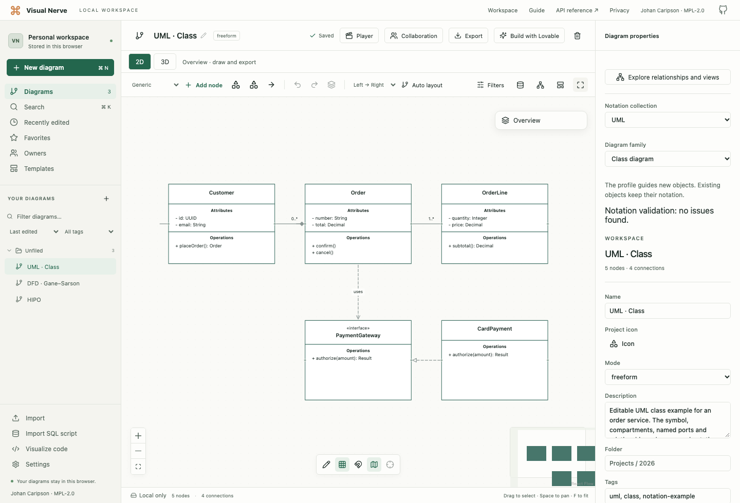
For a connected next element, select a notation object and use its + → Add next menu. The choices stay in that object’s collection and diagram family. A new symbol uses its recommended size and empty sections, with a starting relationship appropriate to the two roles. Review and name that relationship in Properties. Add owner-bound symbols, such as a UML port or BPMN boundary event, through the palette and set Attached to.
Edit information inside a symbol
Under Notation properties, the chosen symbol exposes its own fields, such as a HIPO module number, DFD process number, UML stereotype or BPMN event definition. Where a symbol has sections, edit Section name and Entries, one per line. Add section and Remove section change that object’s saved sections.
Some symbols have fixed regions: an overview IPO has three sections, a detail IPO has four, and a choreography activity has three. Keep their information in those regions rather than adding unrelated sections. Enlarge the object when its entries need more space.
Use Attached to for a port, execution specification or boundary event that belongs to another object. Related module or classifier records a reference to another saved object. These fields store actual object references; writing another object’s name in a title does not create a reference.
An attached symbol moves with its owner. Copying an owner includes its attachments; copying an attached symbol includes its owner. Deleting the owner also deletes its attached symbols. Position the attachment on the appropriate boundary or lifeline, and review that placement after resizing the owner.
Numeric notation fields and fields with strict syntax keep a local draft while you type. Press Enter or move focus away to commit a valid value; Escape restores the saved value. An invalid intermediate number or multiplicity is not written to the diagram. Timing observations use Apply timing observations after you enter increasing time | state lines.
Add named port adds a connection point with a label, side and fractional position from 0 to 1 along that side. A relationship can name its source and target ports. This is useful for sequence messages at different heights, component interfaces and explicit routes.
Before removing a port or changing its direction, select its relationships and choose compatible endpoints. The editor rejects a change that would leave a relationship pointing to a missing or incompatible port.
Titles still support F2, double-click or double-tap editing. Node background color controls the fill, while Color controls the accent. See ordinary editing for keyboard and touch behavior.
New starting sets use the current Appearance for their backgrounds in both 2D and 3D. A custom background remains the exact saved color when Appearance changes. Select Use theme background in Properties to clear that custom fill; this also works for examples created with the earlier pale background. The fill follows the symbol’s outline, so rounded corners and open shapes do not acquire a rectangular background. Text over an open region or outside a filled symbol follows the canvas’s theme for readability. UML boundaries and frames keep their visible relief in 3D while their centers remain open.
Read and edit relationship ends
Select a connection to choose Notation collection and Relationship notation in its Properties. The notation supplies its line and end decoration: for example a UML composition diamond, generalization triangle, BPMN message-flow circle and open arrow, or a DFD data-flow arrow.
Name the relationship and, where useful, its source and target roles or multiplicities. 1, 0..1 and 1..* describe UML association ends; they do not set a simulation arrival rate. Guards, message numbers and BPMN conditions describe the modeled design.
Choose Default appearance in the object’s or relationship’s Notation collection selector to clear that notation. Clearing a document profile leaves existing objects’ notation intact. Changing the document family guides the palette and review; it does not convert the contents into a different modeling language.
An object uses one symbol vocabulary at a time. Choosing a notation symbol clears its IBM flowchart symbol, and choosing an IBM symbol clears its notation. The saved title, fill and ordinary object identity remain.
Review, save and explain
Document Properties shows Review notation when the draft has issues. Review the named objects, ports, attachments and relationship contexts. These checks find selected structural problems; a clean report does not prove that a business process or software design is correct.
The same saved symbols can be inspected in 3D . Use 2D for precise arrangement and visual exports. Native JSON preserves the notation model and its references; keep it when another copy must remain editable in Visual Nerve. See export formats for the fidelity of each format.
The collections provide editable graphical modeling. They do not execute UML or BPMN, evaluate OCL, generate code, or provide UML XMI or BPMN XML interchange. See each collection guide for its specific coverage and primary sources.
For live editing, all participants need current notation support. An older room rejects adding notation; update participants and create a new room from the retained diagram. Collaboration compatibility and approval steps .